ProjectExplorer 4 for Autodesk Civil 3D
Tutorials | Editing the Civil 3D Model
Tutorials
Editing the Civil 3D Model
This tutorial demonstrates the use of the editing tools in ProjectExplorer to apply some design changes to pipes and corridors.
We'll use the new Multiple Part Swap feature to edit a Pipe Network, then use the Assembly editing tools to widen the carriageway on a Corridor. Optionally, we'll then update the reports previously generated from this tutorial in the simplest way possible - with a single mouse button click.
Getting Started
In Autodesk Civil 3D, Open the standard Civil 3D sample drawing: Intro-1.dwg. You will have saved this drawing at the end of the first part of this tutorial.
This drawing is part of the standard Civil 3D installation, and can generally be found in the following folder:
C:\Program Files\Autodesk\AutoCAD 2018\C3D\Help\Civil Tutorials\
If you wish to learn about the report updating capabilities of the Object Sets, we recommend working through the Working with Object Sets tutorial before commencing this tutorial. In this case, you should use the end result from that tutorial as your starting point for the following tasks.
Preparing to review and edit a pipe run
First, let's prepare the ProjectExplorer window by nominating the path of a specific pipe run that we'd like to edit:
- From the Civil 3D ribbon, select the Add-Ins tab and open the ProjectExplorer window.
- Select the Pipe Networks tab in the ProjectExplorer window.
- Check that the pipe network Profile View settings are still set to:
- Start Structure : Structure - (2)
- End Structure : Structure - (8)
- Comparison Surface : First Street - (1)
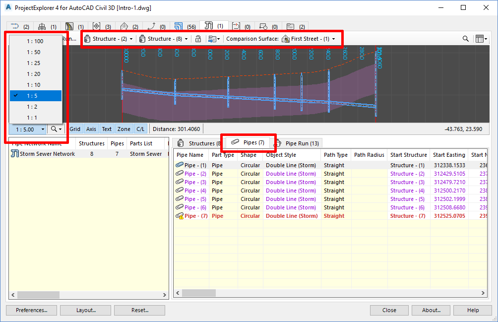
- Increase the vertical exaggeration of the profile view to 1:5.
- Select Pipes from the part category tab as indicated below.
Swapping Multiple Parts in a Pipe Network
ProjectExplorer allows multiple pipe network parts to be swapped in a single operation. Let's use this tool now to make some changes to the pipe diameters on our pipe run.
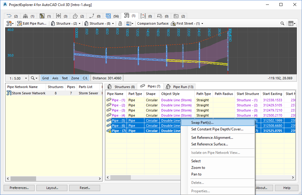
- Select the following pipes in the Pipes list in the ProjectExplorer window.
- Pipe - (5)
- Pipe - (6)
- Pipe - (7)
- Right-click the selected pipes and select Swap Part(s) from the right-click menu.
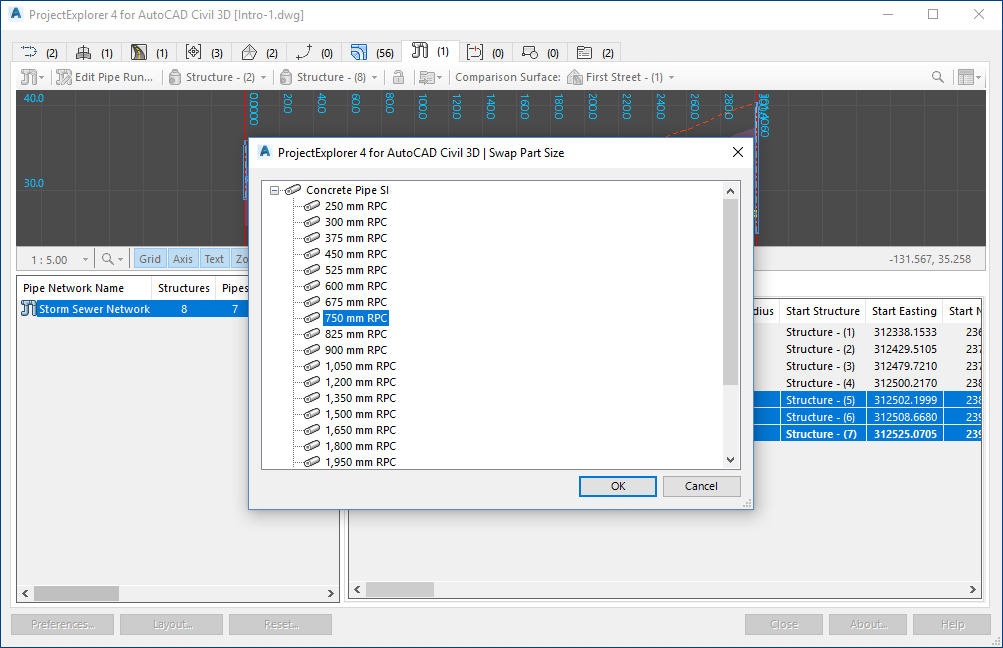
- From the Swap Part Size dialog, select the 750mm RPC concrete pipe and click OK.
- Right-click Pipe - (4) from the Pipes list in the ProjectExplorer window, and select Swap Part(s) from the right-click menu.
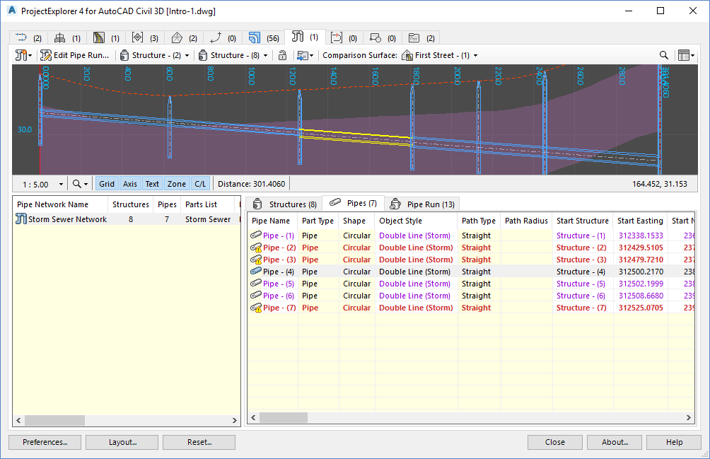
- From the Swap Part Size dialog, select the 600mm RPC concrete pipe and click OK.
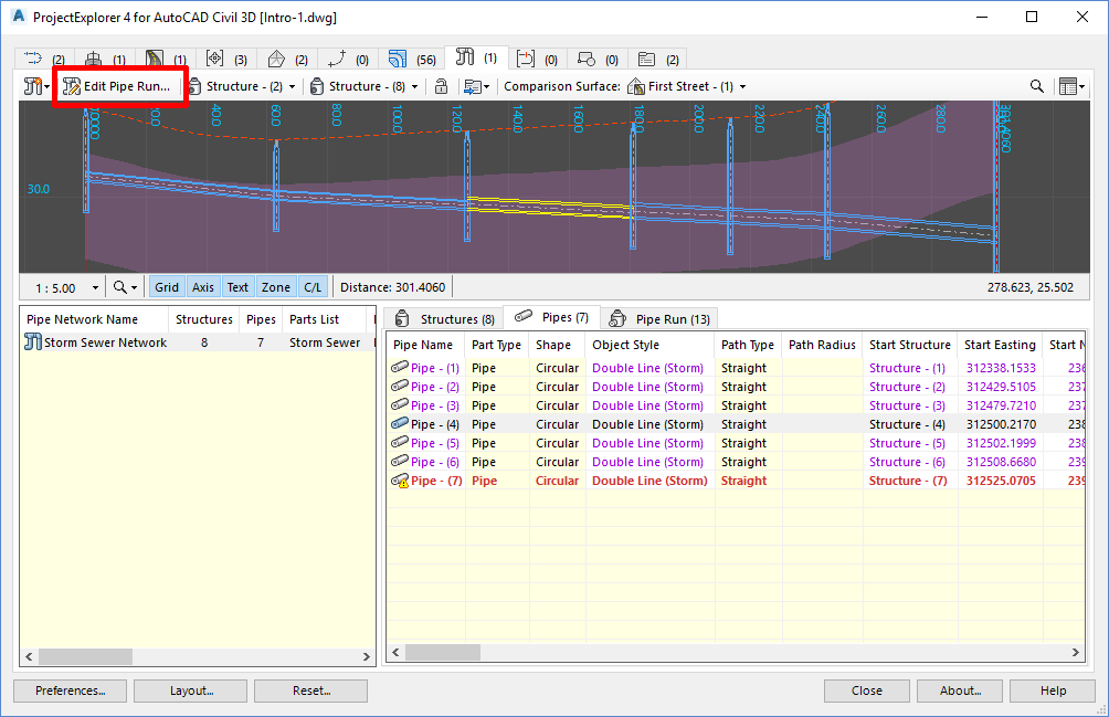
The pipe run should now resemble the one shown in the following image.
Adjusting the pipe slope along a pipe run
ProjectExplorer allows the slope of an entire pipe run to be adjusted in a single operation. Let's try this now:
- Check that the pipe network profile view settings are still set to:
- Start Structure : Structure - (2)
- End Structure : Structure - (8)
- Comparison Surface : First Street - (1)
- Change the vertical exaggeration of the pipe network profile view to 1 : 10 to make it easier to see the pipe slope changes that we will apply.
- Press the Edit Pipe Run button in the main toolbar of the Pipe Networks tab.
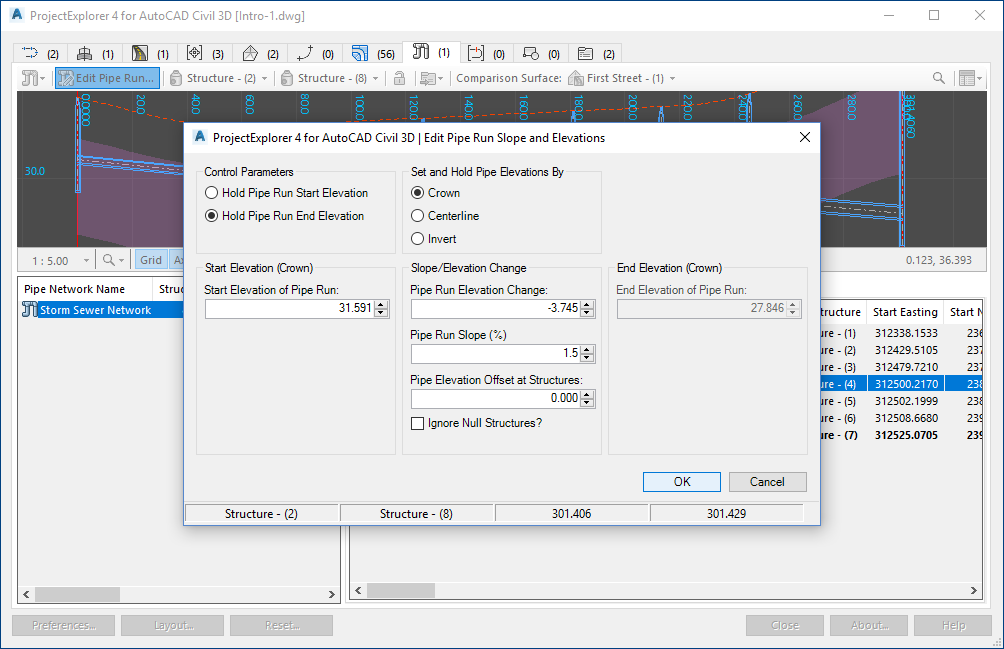
- The Edit Pipe Run Slope and Elevations dialog opens.
- Our aim is to adjust the start elevation of the pipe run but hold the elevation of the pipe at the end of the pipe run. Also, we need to apply a constant slope of 1.5% across all pipes whilst maintaining the crown elevation of each pipe at every intermediate structure.
- Change the pipe run Control Parameters to Hold Pipe Run End Elevation.
- Change the method for Hold Pipe Elevation to the Crown option.
- Change the Pipe Run Slope to 1.5%.
- Click OK to close the dialog and return to the ProjectExplorer window. The pipe run is updated to give the following result.
Note that three pipes in the list are now considered to be in a violated state. Hover your mouse over each violation to discover which design rules have been violated.
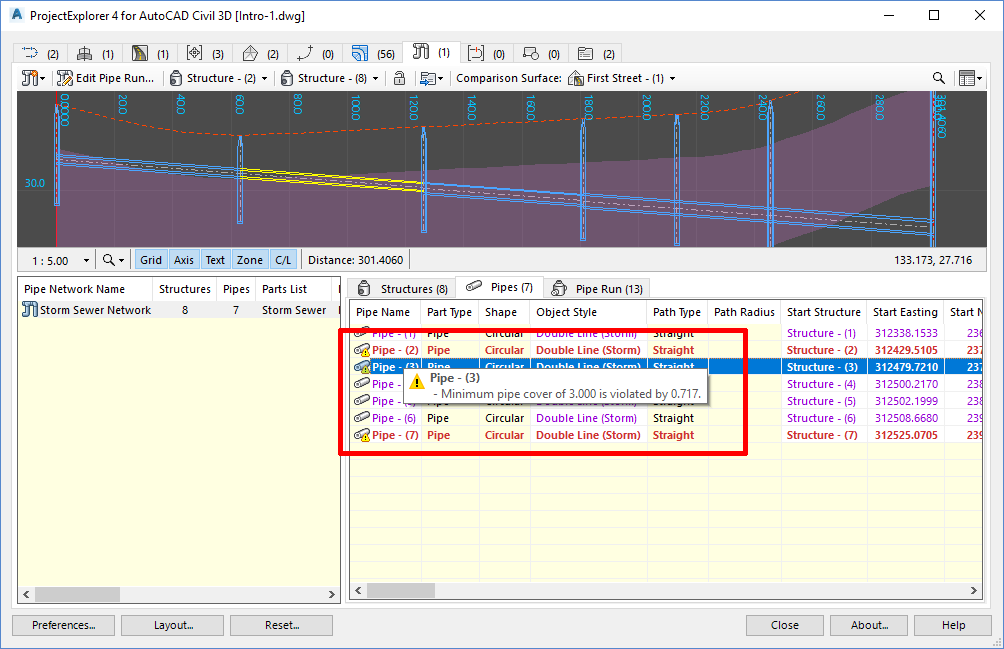
At this point, you might wish to address these violations by carrying out further editing to the pipe network. The violations will be updated after each design change, regardless of whether these edits are carried out in ProjectExplorer or using the Civil 3D user interface.
As further editing is outside the scope of this tutorial, we have now completed the pipe network related portion of this tutorial. Next, we'll apply a design change to a corridor by modifying the width of the main carriageway.
Modifying corridor geometry by editing assemblies from ProjectExplorer
First, we need to ensure that any changes we apply to this assembly are immediately reflected in the associated corridor.
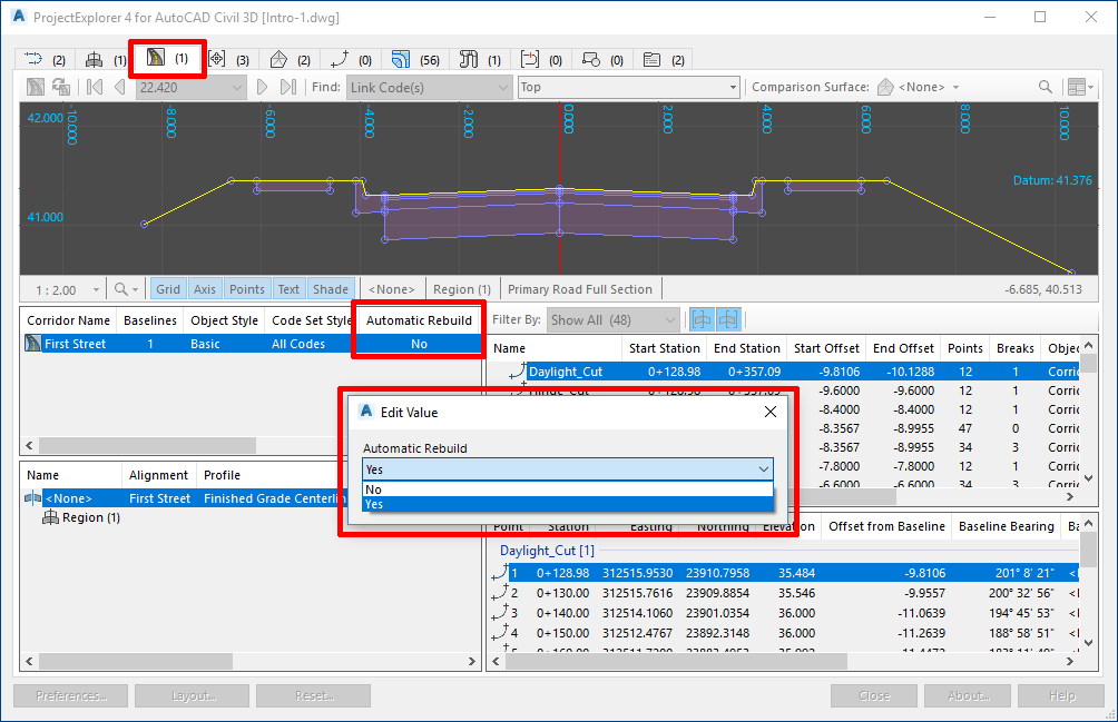
- Select the Corridors tab in the ProjectExplorer window.
- In the corridor list select First Street and scroll across the list until you see the Automatic Rebuild parameter. Double click the existing No value in this field and set it to YES.
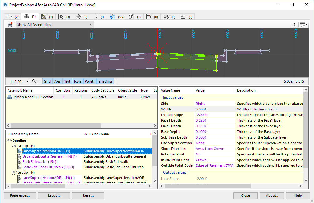
- Select the Assemblies tab in the ProjectExplorer window.
- In the assemblies list select Primary Road Full Section.
- In the subassemblies list for this assembly, select LaneSuperelevationAOR - (19).
- The parameters for this subassembly are displayed and the assembly Section View indicates the geometry of the selected subassembly.
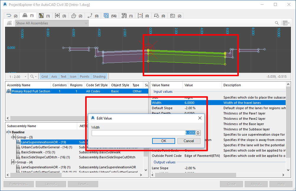
- Double-click the width parameter and change the value from 3.500 to 6.000.
- In the subassemblies list for this assembly, select LaneSuperelevationAOR - (19) (1), and make a similar change to the width parameter, increasing the value to 6.000.
- Note that the changes we have applied here are immediately reflected in both the Section View and in the AutoCAD viewport.
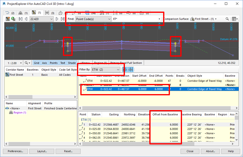
- Select the Corridors tab in the main ProjectExplorer window.
- In the corridor Section View toolbar, select Point Code(s) from the Find drop down list and select ETW from the list of available codes. This will highlight the location of the updated ETW point codes in the section view. TIP: Highlight the location of multiple point codes by entering a comma delimited list into this field. It is also possible to input partial point codes such as ET*.
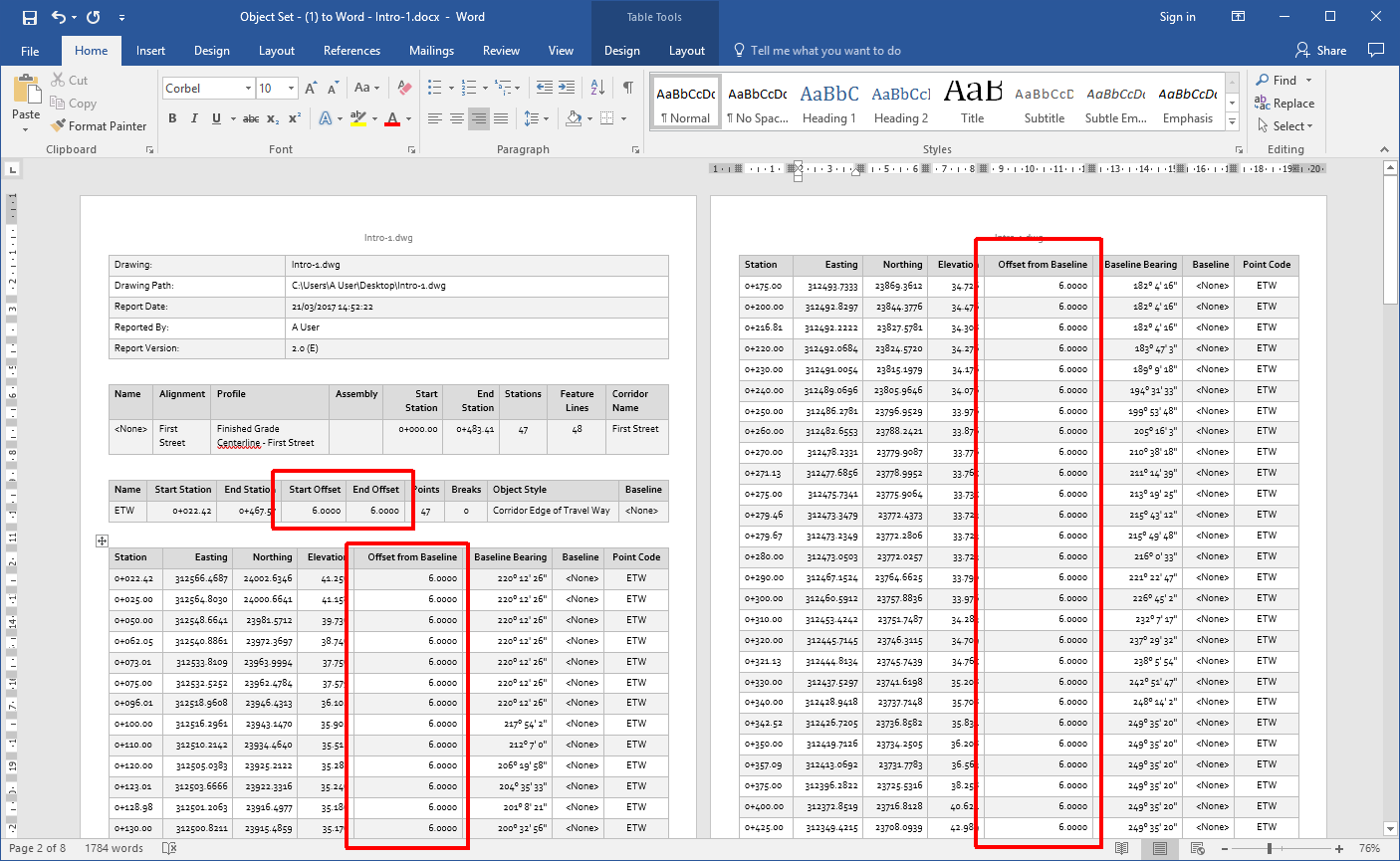
- In the corridor feature lines list, scroll down to find and select ETW from the list. Verify that the baseline offset is now set to 6.000.
We have now completed the necessary design changes to our Civil 3D model. Let's now update our previously generated reports to include the updated design - with just a few simple steps.
Updating the reports
After any design change in Civil 3D, previously generated reports or other exported files produced by the Object Sets feature in ProjectExplorer can be updated in just a few simple steps.
The remainder of this tutorial is only applicable if you previously worked through the Working with Object Sets tutorial and used the end result from that tutorial as your starting point for the preceeding tasks.
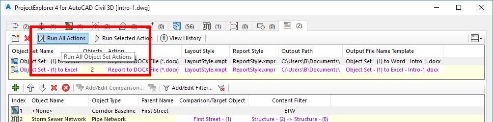
- Select the Object Sets tab in the main ProjectExplorer window.
- Press the Run All Actions button. This will update both reports with the latest design changes that we applied to the pipe network and corridor.
- Review the updated reports now to see the result of those changes.
The ProjectExplorer Output History Window
ProjectExplorer keeps a persistent record of every report it has generated from a given AutoCAD drawing. These records can be reviewed from the Output History window. This dialog can be accessed in two ways:
- By pressing the View History button in the main toolbar of the Object Sets tab in the ProjectExplorer window.
- By accepting the option to "review the results in the Output History window" immediately after the Run All Actions or Run Selected Action buttons are pressed.
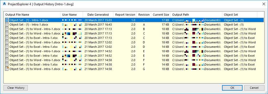
From this dialog it's possible to see the path and name of the output file of every generated report, along with the file creation date and the name of the user who generated the report.
Double-click any listed entry to directly open the associated report file. Alternatively, right-click any listed entry to open the output path of the file in Windows Explorer or to remove the entry from the Output History list.
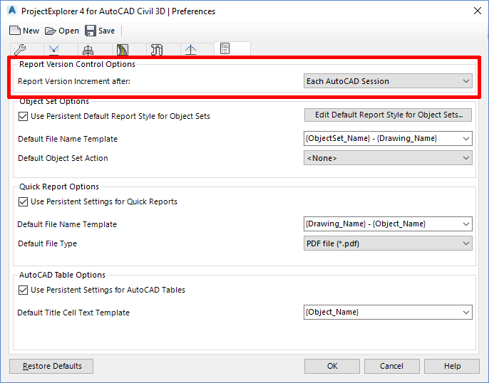
Version Control in ProjectExplorer
Note that a unique Report Version and Revision number is assigned to every report generated from ProjectExplorer. By default these values are incremented in the following scenarios:
- The Report Version is incremented every time a new session of AutoCAD is started.
- The Report Revision is incremented every time a report is updated.
This behaviour may be modified from the ProjectExplorer Preferences dialog which can be opened by pressing the Preferences button in the main ProjectExplorer window.
You have now completed this tutorial.