ProjectExplorer 6 for Autodesk Civil 3D
User Guide | Working with Object Sets
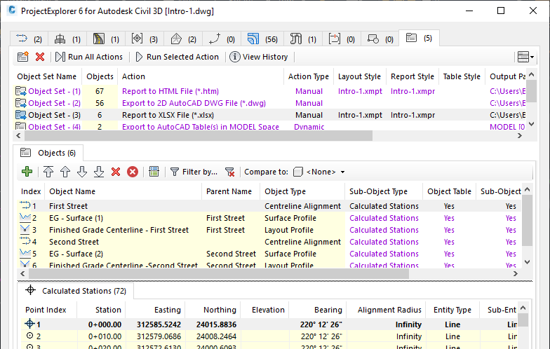
Working with Object Sets
The Object Sets tab in the main ProjectExplorer window allows one ore more sets of objects to be persistently defined in your AutoCAD drawing. Object Sets are particularly useful for automating the generation of one or more reports from your drawing.
Actions may be associated with each Object Set, and these actions can be triggered with just a single mouse click. For example, a report generating action could be used to create a report file using a pre-configured Layout Style, Report Style, Output File Name and Path.
What is an Object Set?
An Object Set is a user-definable list of Civil 3D objects, to which you can assign an action and other related details. Actions can be triggered manually with a single button press or, in some cases, dynamically when ProjectExplorer detects that a dependent part your design has been modified. Object Sets are typically used to automate the production of pre-configured reports, spreadsheets, AutoCAD drawings, or AutoCAD tables, and the exact combination of styles, filters, and output instructions required depends on the type of action and object which is assigned.
Object Set definitions are saved to your drawing persistently, which means that anyone can trigger an action if they have access to the drawing and a copy of ProjectExplorer. There is no limit to the number of Object Sets which can be defined in a single AutoCAD drawing.
Creating an Object Set
Object Sets can be created from the Create Object Set dialog, which can be accessed in two ways.
- Navigate to the Object Sets tab in the ProjectExplorer window, and press the Create Object Set... button.
- Right-click any object in the ProjectExplorer window and select the Add to Object Set > Create Object Set... menu item.
Common Object Set Options
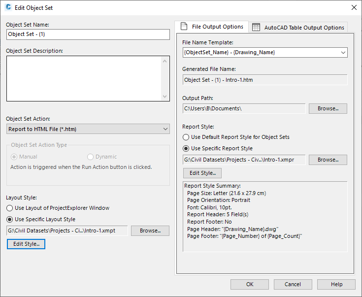
Object Set Name
A unique name must be assigned to each Object Set.
Object Set Description
An optional description may optionally be assigned to each Object Set.
Object Set Action and Action Type
An optional Object Set Action may be assigned to each Object Set. Actions are generally used to automate the process of generating reports, spreadsheets, or AutoCAD tables. The Object Set Action Type parameter determines how the assigned action should be triggered - either manually or dynamically.
The current list of available Object Set Actions in ProjectExplorer is as follows:
| Action | Description |
|---|---|
| None | If no action is assigned to the Object Set, it is purely being used as a selection set to build a display group of objects that need to be monitored for a common purpose. |
| Report to Text File | Use the Report to Text File option to cause an outgoing report file in Text format to be generated when the Run Action button is pressed. Use of this option requires a Layout Style to be selected which determines the layout and file type of the report, and an output path. |
| Report to CSV File | Use the Report to CSV File option to cause an outgoing report file in CSV format to be generated when the Run Action button is pressed. Use of this option requires a Layout Style to be selected which determines the layout and file type of the report, and an output path. |
| Report to HTML File | Use the Report to HTML File option to cause an outgoing report file in HTML format to be generated when the Run Action button is pressed. Use of this option requires a Layout Style to be selected which determines the layout and file type of the report, and an output path. |
| Report to PDF File | Use the Report to PDF File option to cause an outgoing report file in PDF format to be generated when the Run Action button is pressed. Use of this option requires a Layout Style to be selected which determines the layout and file type of the report, and an output path. |
| Report to DOCX File | Use the Report to DOCX File option to cause an outgoing report file in Microsoft Word DOCX format to be generated when the Run Action button is pressed. Use of this option requires a Layout Style to be selected which determines the layout and file type of the report, and an output path. |
| Report to RTF File | Use the Report to RTF File option to cause an outgoing report file in Microsoft Word RTF format to be generated when the Run Action button is pressed. Use of this option requires a Layout Style to be selected which determines the layout and file type of the report, and an output path. |
| Export to 2D AutoCAD DWG File | Use the Report to 2D AutoCAD DWG File option to cause an outgoing AutoCAD DWG file to be generated when the Run Action button is pressed. The generated DWG file will contain native AutoCAD drawing entities only, all of which will be converted to 2d. The resulting drawing should look identical in plan to the source Civil 3D drawing, but will be a fraction of the original drawing size in terms of bytes. |
| Export to AutoCAD Table(s) in MODEL Space | Use the Export to AutoCAD Table(s) in MODEL Space option to cause an AutoCAD table to be generated in Model Space in the current drawing when the Run Action button is pressed. Use of this option requires a Layout Style to be selected which determines the layout of the table content, and a Table Style which determines the style of the table itself. |
| Export to AutoCAD Table(s) in PAPER Space | Use the Export to AutoCAD Table(s) in PAPER Space option to cause an AutoCAD table to be generated in Paper Space in the current drawing when the Run Action button is pressed. Use of this option requires a Layout Style to be selected which determines the layout of the table content, and a Table Style which determines the style of the table itself. |
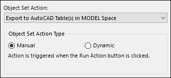
Object Set Action Type
There are two different ways in which an Object Set Action can be triggered:
| Type | Description |
|---|---|
| Manual | In this case, actions are triggered manually when the Run Action or Run All Actions button is pressed. This is the default behaviour and is available for all types of Object Set Action. |
| Dynamic | In this case, actions are triggered dynamically when any associated object is modified in the Civil 3D or ProjectExplorer windows. This action type is currently only supported for Object Set Actions which generate AutoCAD tables. |
The ProjectExplorer window must be open for the Dynamic Action Type to successfully detect changes to objects which are associated with a related Object Set.
Where the ProjectExplorer window is not open, any dynamic actions will be triggered when the ProjectExplorer is next opened. If you are unsure whether a dynamic action has been successfully triggered since a change was made to your design, the Run Action or Run All Actions button may be pressed at any time to manually trigger the action.
Layout Style
When using the Generate Report action, a Layout Style must be assigned to the Object Set. This Layout Style will determine the layout and formatting of the content in the generated report.
File Output Related Options
The file name for the report or spreadsheet file can either be typed in, generated from a list of standard variables, or a combination of the two methods. The drop-down list of variables allows all or part of the filename to be generated from a list of variables such as the selected object name, object set name, the current drawing name, the current date, user name, computer name, and AutoCAD or ProjectExplorer version.
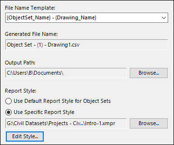
Output Path
When using the Generate Report action, an output path must be specified to define where the generated report file should be created.
When variables or combinations of variables are typed into the File Name Template field, the resulting file name is previewed in the field directly beneath it.
Report Style
A report style is required to define the page size, page orientation, page margins, report header, page header and page footer settings for the generated report or spreadsheet. Press the Browse button to select a previously created Report Style from a file to apply to the generated report or spreadsheet. Alternatively, press the Edit Style button to edit or define a style to use.
AutoCAD Table Related Options
This set of options applies specifically to the creation of static or dynamic AutoCAD tables in model space or paper space.
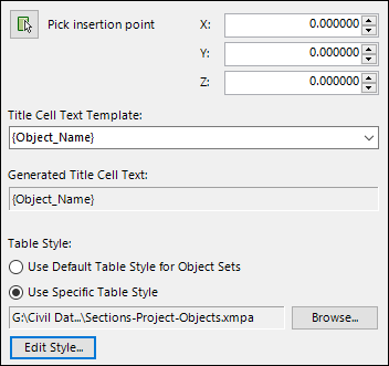
Pick Insertion Point
Use this option to determine the location of the top left corner of the AutoCAD table or tables created by each Object Set. The location can either be specified by typing an XY coordinate into the window, or by picking a point in the AutoCAD viewport.
Title Cell Text
The text for the title cell of the AutoCAD table can either be typed in, generated from a list of standard variables, or a combination of the two methods. The drop-down list of variables allows all or part of the title cell text to be generated from a list of variables such as the selected object name, object set name, the current drawing name, the current date, user name, computer name, and AutoCAD or ProjectExplorer version.
When variables or combinations of variables are typed into the Title Cell Template field, the resulting title cell text is previewed in the field directly beneath it.
Table Style
A Table Style is required to define the border color, font size and type, cell margins, and general visual style of any generated AutoCAD tables. Press the Browse button to select a previously created Table Style from a file to apply to the generated report or spreadsheet. Alternatively, press the Edit Style button to edit or define a style to use.
Adding Objects to an Object Set
There are two available methods for populating an Object Set with Civil 3D objects:
- Navigate to the Object Sets tab in the ProjectExplorer window, and press the Add Object(s) to Object Set... button.
- Right-click any object in the ProjectExplorer window and select the Add to Object Set menu item, then select the relevant entry for the Object Set that you wish to add the object to.
Managing Object Set Items
When a Civil 3D object is added to an Object Set, an Object Set Item is created. An Object Set can contain any number of Object Set Items, and Object Set Items can be re-ordered, duplicated and removed from an Object Set.
Applying Filters
There are a number of filtering options available for some Object Set Items depending on the type of Civil 3D object referenced. For instance:
- For alignments or profiles, the start and end station range can be specified.
- For corridors, feature lines can be filtered by point code(s).
- For pipe runs, the start and end structure can be modified.
Suppresing the Object Table or Sub-Object Table
For each item in an Object Set, at least two tables will be written to a table, report, or spreadsheet by default:
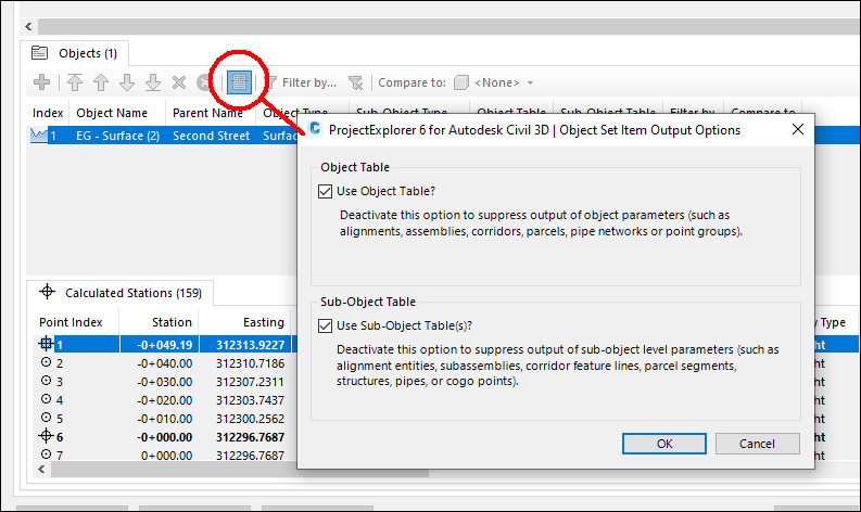
- The Object Table - this is the table which includes parameters of the enclosing object, such as an alignment, corridor, parcel, or pipe network.
- The Sub-object Table - this is the table which includes parameters at sub-object level, such as alignment stations or entities, corridor feature lines and points, parcel segments, or pipe network structures and pipes.
With these options you can decide to suppress the creation of either the Object Table or Sub-Object Table. This is useful for situations where you might want to (for instance) create a report or table which includes a list of structures (which would appear in a Sub-object Table), but you do not need to see details of the pipe network (which would appear in the Object Table).
Changing the Sub-Object Type
For some Civil 3D object types, there is a choice of available sub-object types for a listed Object Set Item. For example, for alignments it is possible to generate a report which includes calculated stations, alignment entities, alignment PIs, or superelevation critical stations.
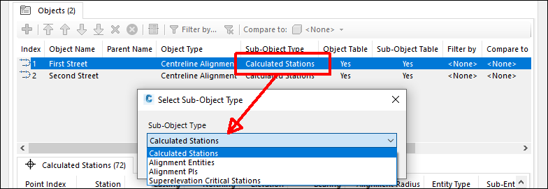
For supported object types, the sub-object type can be changed after an object has been added to an Object Set. To change a sub-object type, simply double-click any editable sub-object type and select one of the available items from the list.